Spindle Rigidity Testing
Spindle rigidity refers to a spindle’s ability to resist deformation under external force, typically expressed in N/μm. The formula for stiffness is as follows: Spindle Rigidity (K) = Applied force (F) ÷ Displacement (δ).
K = Rigidity (N/μm)
F = Applied Force (N)
δ = Displacement (μm)
Insufficient spindle rigidity can result in elastic deformation during cutting, leading to machining vibrations, reduced dimensional accuracy, poor surface finish, and uneven bearing loads that compromise long-term stability. A high-rigidity spindle improves cutting stability, minimizes machining errors and tool wear, and ensures consistent quality during long-cycle precision machining. For reference, measurement diagrams are shown in Fig. 1, 2.
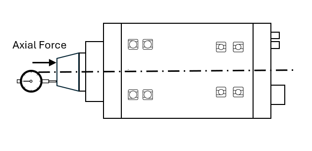
Fig. 1 Spindle Axial Rigidity Test Diagram
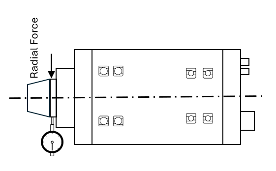
Fig. 2 Spindle Radial Rigidity Test Diagram
In spindle design and selection, radial rigidity and axial rigidity are critical performance indicators that directly affect machining accuracy, surface finish, and tool life. Standard rigidity values vary depending on the spindle type (e.g., built-in motor spindles, belt-driven spindles, direct-drive spindles), application type (milling, grinding, turning), and machine configuration (high-speed or high-rigidity spindles).
Below are commonly referenced industry benchmarks, useful for evaluating spindle performance during design, testing, or selection to enhance machining stability and precision.
|
Spindle Applications |
Radial Rigidity(N/μm) |
Axial Rigidity(N/μm) |
|
High-Speed Machining Spindle |
50 ~ 150 |
100 ~ 300 |
|
Standard Milling Machine Spindle |
150 ~ 300 |
300 ~ 800 |
|
High-Rigidity Grinding Spindle |
300 ~ 800 |
500 ~ 1000 |
|
Precision Lathe Spindle |
200 ~ 500 |
500 ~ 1000 |